
Rotary Encoders: Types, Specifications & Applications
What is a Rotary Encoder?
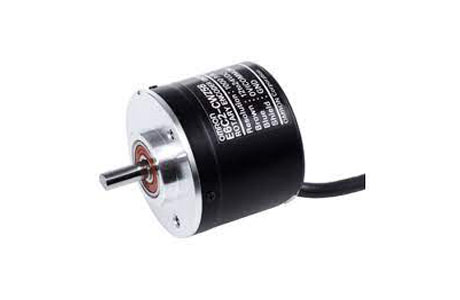
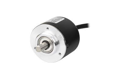
A rotary encoder is a device that converts the rotational motion of a shaft into an electrical signal. It is commonly used to measure the position, speed, or direction of the rotation. Rotary encoders provide valuable feedback for controlling various machinery and equipment, ensuring precise and efficient operation.
They come in different types, such as optical, magnetic, and offer different levels of resolution and accuracy. Rotary encoders are widely used in industrial automation, robotics, automotive systems, consumer electronics, and many other applications.
So, let’s dive in and start the rotary encoder basics together!”

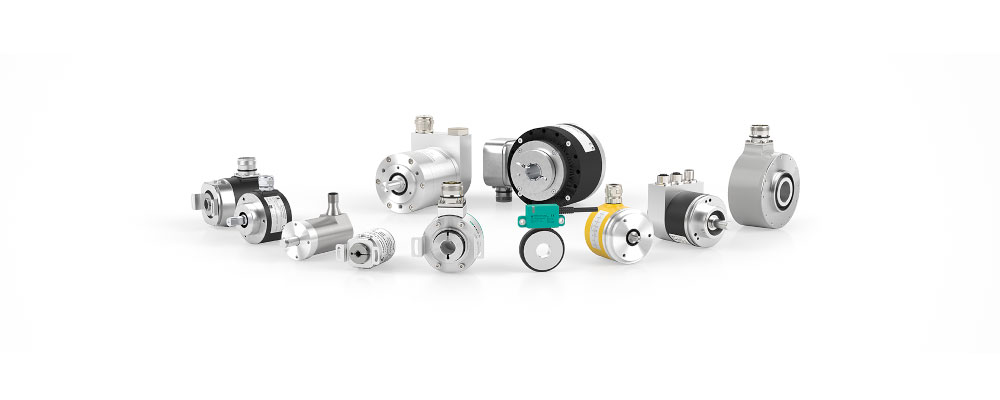
Rotary Encoder Types
Optical Rotary Encoder: This type uses a light source, a patterned disc, or a strip to generate signals. Light sensors detect changes in light intensity as the disc rotates, providing position or speed feedback.
Magnetic Rotary Encoder: Magnetic encoders use magnets or magnetized discs to sense rotational movement. Hall effect sensors or magnetic sensors detect changes in the magnetic field, generating electrical signals for a position or speed measurement.
Capacitive Rotary Encoder: These encoders rely on changes in capacitance to measure rotation. It utilizes electrodes or plates that create a capacitor with a rotating shaft or target. Changes in capacitance are then used to determine position or speed information.
Incremental Rotary Encoder: Incremental encoders generate pulses as the shaft rotates. Each pulse represents a fixed angular displacement, allowing for a relative position or speed measurement. They do not provide absolute position information.
Absolute Rotary Encoder: Absolute encoders provide a unique digital code for each position of the shaft. They can directly determine the absolute position, offering accurate feedback without the need for reference points.
Difference between Absolute and Incremental Encoder
The major differences between absolute and incremental encoders are as follows:
Position Information: Absolute encoders provide direct and unique position information for each position of the encoder shaft. In contrast, incremental encoders provide relative position information in the form of pulses or counts, which represent changes in position.
Absolute vs. Relative Positioning: Absolute encoders can determine the exact position of the encoder shaft without any reference point. On the other hand, incremental encoders can only track changes in position relative to a known starting point or reference position.
Resetting Position: Absolute encoders remember position even after power loss, instantly providing the exact position upon power-up. Incremental encoders need a reference point or known starting position to reset position since they do not retain absolute position information.
Complexity and Cost: complex and expensive due to the need for additional circuitry to provide direct position information. In contrast, incremental encoders are simpler and more cost-effective, offering relative position information with less complex circuitry.
Application Specifics: Absolute encoders are suitable for applications requiring precise position knowledge, such as robotics, CNC machines, and positioning systems. Incremental encoders are commonly used for tracking relative motion, speed control, or counting rotations in various applications.
Incremental Rotary Encoder Principle
The principle of an incremental rotary encoder is based on the generation of electrical pulses as the encoder shaft rotates. Here’s a simplified explanation of how an incremental rotary encoder works:
Disc with Pattern: The encoder has a disc with evenly spaced slots or transparent and opaque sections. This patterned disc rotates along with the shaft.
Light Source and Sensors: LED shines through disc slots or sections. On the other side, light sensors detect the changes in light intensity caused by the rotating disc.
Pulse Generation: As the slots or sections pass by the light sensors, the amount of light reaching the sensors changes. This change in light intensity is converted into electrical signals, resulting in the generation of pulses.
Pulses per Revolution: The count of electrical signals produced by an encoder for each full rotation of its disc. This count is determined by the number of slots or sections on the disc. The more slots or sections there are, the higher the PPR and the finer the resolution of the encoder.
Relative Position Tracking: Incremental encoders track changes in position or relative movement. By counting the number of pulses generated, the encoder can determine the relative position or movement of the shaft.
Index Pulse: Some incremental encoders have an additional index pulse, also known as a reference mark or Z pulse. This pulse occurs once per revolution and provides a reference point to reset the position to a known reference.
Absolute Rotary Encoder Working Principle
Here’s a simplified explanation of how an absolute rotary encoder works:
Disc with Binary Pattern: It consists of concentric rings or tracks divided into segments with binary patterns (0s and 1s). The patterns represent a specific position on the disc.
Sensors: Sensors, such as optical or magnetic sensors, are positioned to read the binary pattern on the disc. Each sensor corresponds to a specific track on the disc.
Binary Code Reading: The sensors read the binary pattern on the disc and convert it into electrical signals.
Binary to Digital Conversion: The electrical signals are processed to convert the binary pattern into a unique digital code. This digital code represents the absolute position of the encoder shaft.
Position Determination: The digital code is used to determine the exact position of the encoder shaft. Each unique code corresponds to a specific position on the disc, allowing for accurate position feedback.
Rotary Encoder Specifications
Certainly! Here’s an explanation of five common specifications to consider when selecting a rotary encoder:
Resolution: Resolution refers to the number of pulses or counts per revolution (PPR or CPR) that the encoder can generate. A higher resolution allows for more precise position or movement detection. For example, an encoder with 1000 PPR can detect smaller increments of rotation compared to an encoder with 100 PPR.
Operating Voltage: This specification indicates the range of voltage within which the encoder can operate reliably. It’s important to ensure Similarity with the power supply used in your system. For instance, if your system operates at 5V, you should choose an encoder that supports a 5V operating voltage.
Output Signal Type: Rotary encoders can provide different output signal types, such as digital (TTL, CMOS) or analog (current, voltage). Consider the requirements of your system and ensure Similarity. For example, if your system requires a digital output signal, you would select an encoder that provides a digital output.
Environmental Protection: Environmental protection ratings, like IP (Ingress Protection) ratings, indicate an encoder’s resistance to dust, moisture, and other environmental factors. Consider the level of protection required for your application. Higher IP ratings indicate better protection against environmental conditions.
Operating Temperature Range: The operating temperature range specifies the minimum and maximum temperatures within which the encoder can function reliably. Ensure that the range matches the environmental conditions of your application. Choose an encoder with a wider operating temperature range for reliable performance in applications with extreme temperatures.
How to Use Rotary Encoder
To use a rotary encoder, you can follow these general steps:
Connect the Encoder: Establish the physical connection between the rotary encoder and your system or device by connecting the appropriate wires. This typically involves connecting the encoder’s output signals (A, B, and Z) to the corresponding input pins on your control device.
Power Supply: Connect the encoder to a power source that meets the voltage requirements specified by the manufacturer for proper operation.
Determine the Encoder Type: Determine the encoder type (incremental or absolute) to accurately interpret its output signals.
Read the Output Signals: Depending on the encoder type, read and interpret the output signals produced by the encoder. For an incremental encoder, these signals typically indicate the direction and amount of rotation. Absolute encoders provide direct position information.
Process the Encoder Data: Analyzing and interpreting the output signals or position information for further system actions.
How to Use Rotary Encoder as Potentiometer
–> To use a rotary encoder as a potentiometer:
–> Connect the encoder’s output signals to your system.
–> Understand how the signals represent rotation or position.
–>Define the desired range and resolution for the virtual potentiometer.
–> Translate the encoder’s signals into values that match the potentiometer position.
–> Update your system with the converted values.
–> Implement debouncing if needed to ensure reliable signal detection.
Conclusion
Rotary encoders provide valuable feedback on shaft rotation or position. They come in various types, including incremental and absolute encoders, with different advantages. Understanding their principles, specifications, and maintenance is crucial.


Our Rotary Encoders Related Blogs
1. Rotary Encoders Terminologies
2. Rotary Encoders with Arduino
3. Top Rotary Encoder Manufacturers
4. Rotary Encoder Basics