| Rated supply voltage | 24 VAC (50/60 Hz)
12 to 24 VDC (Ripple 20% max.) |
| Operating voltage range | 85 to 110% of rated supply voltage |
| Connection method | 8-pin round socket |
| Mounting method | Flush mounting / Surface mounting |
| Power consumption | Approx. 5.1 VA/Approx. 2.4 W |
| Time ranges (Number of ranges) | 10 |
| Time ranges | 0.001 to 9.999 s
0.01 to 99.99 s
0.1 to 999.9 s
1 to 9999 s
0.1 to 999.9 min
1 to 9999 min
0.1 to 999.9 h
1 to 9999 h
1 s to 99 min 59 s
1 min to 99 h 59 min |
| Input method | No-voltage (NPN)/Voltage (PNP) input (selectable) |
| Output modes | A: Signal ON delay (Ⅰ)
A-1:Signal ON delay (Ⅱ)
A-2: Power ON delay (Ⅰ)
A-3: Power ON delay (Ⅱ)
b: Repeat cycle (Ⅰ)
b-1: Repeat cycle (Ⅱ)
d: Signal OFF delay
E: Interval
F: Cumulative
Z: ON/OFF-duty adjustable flicker
S: Stopwatch
toff: Flicker OFF start (Ⅰ)
ton: Flicker ON start (Ⅰ)
toff-1: Flicker OFF start (Ⅱ)
ton-1: Flicker ON start (Ⅱ) |
| Reset system | Power reset (depending on output mode)/Automatic reset (depending on output mode)/External reset/Manual reset |
| Timer mode | Elapsed time (UP) and remaining time (DOWN) (selectable) |
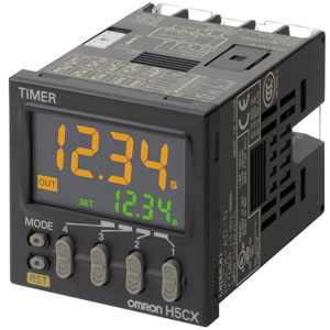
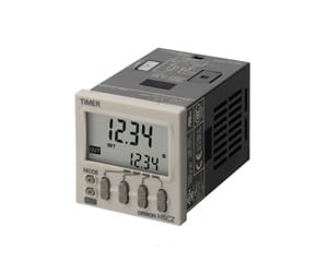
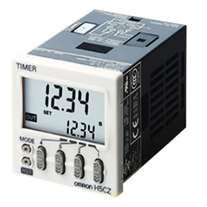
| Display method | 7-segment negative transmissive LCD 4 digit |
| Character height | Present value: 12 mm (Red, green or orange programmable)
Set value: 6 mm (green) |
| Ambient temperature range | -10 to 55 ℃ (with no freezing or condensation)
When mount timer side by side: -10 to 50 ℃ (with no freezing or condensation) |
| Ambient humidity (Operating) | 25 to 85% |
| Accuracy of operating time | Power-ON start: ±0.01% ±0.05 s max. (The values are based on the set value.)
Signal start: ±0.005% ±3 ms max. (The values are based on the set value. The value is applied for a minimum pulse width of 1 ms.) |
| Setting error | Power-ON start: ±0.01% ±0.05 s max. (The values are based on the set value.)
Signal start: ±0.005% ±3 ms max. (The values are based on the set value. The value is applied for a minimum pulse width of 1 ms.) |
| Influence of voltage | Power-ON start: ±0.01% ±0.05 s max. (The values are based on the set value.)
Signal start: ±0.005% ±3 ms max. (The values are based on the set value. The value is applied for a minimum pulse width of 1 ms.) |
| Influence of temperature | Power-ON start: ±0.01% ±0.05 s max. (The values are based on the set value.)
Signal start: ±0.005% ±3 ms max. (The values are based on the set value. The value is applied for a minimum pulse width of 1 ms.) |
| Insulation resistance | Between current carrying terminals and exposed non-current carrying metal parts: 100 MΩ min. (at 500 VDC)
Between non-continuous contacts: 100 MΩ min. (at 500 VDC) |
| Dielectric strength | Between current carrying metal parts and non-current carrying metal parts: 2000 VAC 50/60 Hz 1 min
Between control output, and power supply/input circuit: 1000 VAC 50/60 Hz 1 min
Between non-continuous contacts: 1000 VAC 50/60 Hz 1 min |
| Impulse withstand voltage | Between power terminals: 1.0 kV
Between current carrying terminals and exposed non-current carrying metal parts: 1.5 kV |
| Noise immunity | Between power terminals: ±1.5 kV
Between input terminals: ±600 kV
square-wave noise by noise simulator, pulse width: 100 ns/1 µs, 1-ns rise |
| Static immunity | Mulfunction: 8 kV, Destruction: 15 kV |
| Vibration resistance | Destruction: 10 to 55 Hz, 0.75 mm single amplitude each in 3 directions for 2 h
Malfunction: 10 to 55 Hz 0.35 mm single amplitude each in 3 directions for 10 min |
| Shock resistance | Destruction: 300 m/s2, 3 times each in 3 axes each directions
Malfunction: 100 m/s2, 3 times each in 6 directions |
| Degree of protection | IEC IP66, UL508 Type 4X (indoors) (when using the Y92S-29 Waterproof Packing and Y92F-30 Flush Mounting Adapter) |
| Case color | Black (Munsell N1.5) |
| Accessory (sold separately) | Soft Cover: Y92A-48F1
Hard Cover: Y92A-48
Flush mounting adapter: Y92F-30/Y92F-45/Y92F-38
Waterproof packing: Y92S-29
Replacement Front Panel: Y92P-CXT4S/Y92P-CXT4G/Y92P-CXT4B |
| Ambient temperature range | -10 to 55 ℃ (with no freezing or condensation)
When mount timer side by side: -10 to 50 ℃ (with no freezing or condensation) |
| No-voltage input (Solid state input) | Short-circuit (ON) impedance: 1 kΩ max. (Leakage current (0 Ω): Approx. 12 mA)
Short-circuit (ON) residual voltage: 3 V max.
Open circuit impedance: 100 kΩ min.
(The DC voltage must be 30 VDC max.) |
| No-voltage input (Contact input) | Use contact which can adequately switch 5 mA at 10 V |
| No-voltage input (Applicable two-wire sensor) | Leakage current: 1.5 mA max.
Switching capacities: 5 mA min.
Residual voltage: 3.0 VDC max.
Operating voltage: 10 VDC |
| Voltage input | High level: 4.5 to 30 VDC
Low level: 0 to 2 VDC (Input resistance 4.7 kΩ) |
| Control output (Solid state output) | 1 pointTransistor output (NPN open collector)
Switching capacities: 30 VDC max., 100 mA max.
Residual voltage: 1.5 V (Capacity value 1 V)
Leakage current: 0.1 mA max. |
| Power reset | Minimum power-opening time: 0.5 s (except for A-3, b-1, F, ton-1 and toff-1 mode) |
| Key protect method | Key protect Switch |
| Memory backup method | EEP-ROM (number of writes: 100,000 operations min., Service life: 10 years min.) |
| Weight | Main Unit: Approx. 115 g |