
In sourcing discussions, H3YN-4-Z-DC24 is often placed next to Omron SMPS 24V 10A, Omron H3Cr A8 Ac100 240 Dc100 125 and Autonics Timers so procurement teams can align budgets and technical requirements effectively.
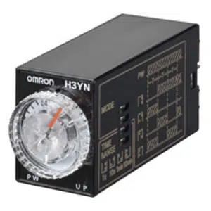
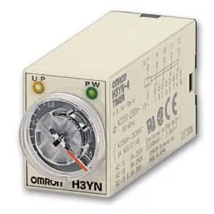
Omron H3YN-4-Z DC24 Timer
The Omron H3YN-4-Z DC24 Timer is designed for precise timing control with an allowable voltage variable range of 85 to 110% of the power supply voltage. The model supports a reset voltage within 10% max. of rated supply voltage and offers 4 selectable time ranges for flexible operation. With a 4PDT time-limit control output, 14-pin round socket connections. Manufactured by Omron, listed under Omron Timers, and part of the H3YN Series.

| Brand | Omron |
| Product | Timers |
| Model Number | H3YN-4-Z DC24 |
Omron H3YN-4-Z DC24 Timer - Technical Specifications
| Specification | Value |
|---|---|
| Rated power supply voltage | 24 VDC If power supply incorporates a single-phase full-wave rectifier. |
| Allowable voltage variable range | 85 to 110% of the power supply voltage |
| Power consumption | Relay ON: Approx. 1.1 W (at 24 VDC)/Relay OFF: Approx. 0.1 W (at 24 VDC) |
| Reset voltage | 10% max. of rated supply voltage |
| Number of time ranges | 4 |
| Operation mode | ON delay, Interval, Flicker OFF start, Flicker ON start |
| Control output (Type) | Time-limit: 4PDT |
| Control output (Contact output) | Resistive load: 3 A at 250 VAC (cosφ=1) Minimum applicable load: 1 mA at 1 VDC (failure level: P) |
| Ambient temperature range | Operating: -10 to 50 ℃ (with no icing) Storage: -25 to 65 ℃ (with no icing) |
| Ambient humidity range | Operating: 35 to 85% |
| Accuracy of operating time | ±1% FS max. (±1% ±10 ms in a range of 1 s) |
| Setting error | ±10% FS ±50 ms max. |
| Reset time | 0.1 s max. (including halfway reset) |
| Influence of voltage | ±2% FS max. |
| Influence of temperature | ±2% FS max. |
| Insulation resistance | 100 MΩ min. (at 500 VDC) |
| Dielectric strength | Between current carrying terminals and exposed non-current carrying metal parts: 2000 VAC 50/60 Hz 1 min (Terminal screw sections are not excluded) Between operating power circuit and control output: 2,000 VAC 50/60 Hz 1 min Between contacts of different polarity: 2,000 VAC 50/60 Hz 1 min Between non-continuous contacts: 1,000 VAC 50/60 Hz 1 min |
| Impulse withstand voltage | Between power terminals: 1 kV Between current carrying terminals and exposed non-current carrying metal parts: 1.5 kV |
| Noise immunity | ±1.5 kV square-wave noise by noise simulator (pulse width: 100 ns/1 µs, 1-ns rise) |
| Static immunity | Mulfunction: 4 kV, Destruction: 8 kV |
| Vibration resistance | Destruction: 10 to 55 Hz, 0.75 mm single amplitude each in 3 directions for 1 hour Malfunction: 10 to 55 Hz, 0.5 mm single amplitude each in 3 directions for 10 min |
| Shock resistance | Destruction: 1,000 m/s2, 3 times each in 6 directions Malfunction: 100 m/s2, 3 times each in 6 directions |
| Life expectancy (relay output) | Electrical: 200,000 operations min. (3 A at 250 VAC, resistive load at 1800 operations/h, Room temperature) Mechanical: 10 million operations min. (under no load at 1,800 operations/h) |
| Degree of protection | IP40 |
| Connecting method | 14-pin round socket |
| Case color | Beige |
| Weight | Approx. 50 g |
Related Products