
During technical comparisons, H3Y-2-B-DC12-30M appears alongside Omron Photoelectric Sensor, Omron H3Cr A8 Ac100 240 Dc100 125 and Autonics Timers so engineers assess signal types, ingress protection, and ambient tolerances accurately.
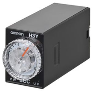
Omron H3Y-2-B DC12 30M Timer
The Omron H3Y-2-B DC12 30M Timer is a solid-state timer designed for precise Power Power ON-delay operation within 1 time range. It supports an allowable voltage variable range of 90 to 110% of the power supply voltage voltage, ensuring stable performance in standard applications. The required reset voltage is 10% min, of rated supply voltage, supporting dependable reset behavior. This timer provides a DPDT time-limit control output, an IP40 degree of protection, and an 8-pin round socket (Push-In Plus Terminal Block). Manufactured by Omron, listed under Omron Timers, and part of the H3Y Series.

| Brand | Omron |
| Product | Timers |
| Model Number | H3Y-2-B DC12 30M |
Omron H3Y-2-B DC12 30M Timer - Technical Specifications
| Specification | Value |
|---|---|
| Rated power supply voltage | 12 VDC If power supply incorporates a single-phase full-wave rectifier. |
| Allowable voltage variable range | 90 to 110% of the power supply voltage |
| Power consumption | Approx. 0.9 W (at 12 VDC) |
| Reset voltage | 10% min, of rated supply voltage |
| Number of time ranges | 1 |
| Operation mode | Power ON-delay |
| Control output (Type) | Time-limit: DPDT |
| Control output (Contact output) | Resistive load: 250 VAC 5 A (cosφ=1) Minimum applicable load: 1 mA at 5 VDC (failure level: P) |
| Operating resetting | Time-limit operation/Self-reset |
| Ambient temperature range | Operating: -10 to 55 ℃ (with no icing) Storage: -25 to 65 ℃ (with no icing) |
| Ambient humidity range | Operating: 35 to 85% |
| Accuracy of operating time | ±1% FS max. |
| Setting error | ±10% FS ±50 ms max. |
| Reset time | 0.1 s max. (including halfway reset) |
| Influence of voltage | ±2% FS ±10 ms max. |
| Influence of temperature | ±2% FS ±10 ms max. |
| Insulation resistance | 100 MΩ min. (at 500 VDC) |
| Dielectric strength | Between current carrying terminals and exposed non-current carrying metal parts: 2000 VAC 50/60 Hz 1 min (Terminal screw sections are not excluded) Between operating power circuit and control output: 2,000 VAC 50/60 Hz 1 min Between contacts of different polarity: 2,000 VAC 50/60 Hz 1 min Between non-continuous contacts: 1,000 VAC 50/60 Hz 1 min |
| Impulse withstand voltage | Between power terminals: 1 kV Between current carrying terminals and exposed non-current carrying metal parts: 1.5 kV |
| Noise immunity | ±1.5 kV square-wave noise by noise simulator (pulse width: 100 ns/1 µs, 1-ns rise) |
| Static immunity | Mulfunction: 4 kV, Destruction: 8 kV |
| Vibration resistance | Destruction: 10 to 55 Hz, 0.75 mm single amplitude each in 3 directions for 1 hour Malfunction: 10 to 55 Hz, 0.5 mm single amplitude each in 3 directions for 10 min |
| Shock resistance | Destruction: 1,000 m/s2, 3 times each in 6 directions Malfunction: 100 m/s2, 3 times each in 6 directions |
| Life expectancy (relay output) | Electrical: 500,000 operations min. (5 A at 250 VAC, resistive load at 1,800 operations/h, Room temperature) Mechanical: 10 million operations min. (under no load at 1,800 operations/h) |
| Degree of protection | IP40 |
| Connecting method | 8-pin round socket (Push-In Plus Terminal Block) |
| Case color | Black |
| Weight | Approx. 50 g |
Related Products