Maintenance teams planning replacements for H3DS-ML-AC-DC frequently review Omron Photoelectric Sensor, Omron H3Cr A8 Ac100 240 Dc100 125 and Autonics Timers to prevent downtime, checking availability and compatibility with existing systems.
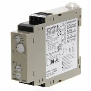
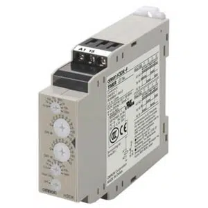
Omron H3DS-ML AC/DC Timer
The Omron H3DS-ML AC/DC Timer is designed for precise timing control with an allowable voltage variable range of 85% to 110% of rated voltage. It operates using Start input signals and a Voltage input method, ensuring dependable triggering across applications. The model supports a reset voltage within 2.4 VDC/VAC max. and offers 7 selectable time ranges for flexible operation. With a SPDT time-limit control output, Terminal blocks connections. Manufactured by Omron, listed under Omron Timers, and part of the H3DS Series.

| Brand | Omron |
| Product | Timers |
| Model Number | H3DS-ML AC/DC |
Omron H3DS-ML AC/DC Timer - Technical Specifications
| Specification | Value |
|---|---|
| Rated power supply voltage | 24 to 230 VAC 50/60 Hz 24 to 48 VDC Ripple 20% max. |
| Allowable voltage variable range | 85% to 110% of rated voltage |
| Input signals | Start |
| Input method | Voltage input |
| Voltage input | High level: 20.4 to 253 VAC/20.4 to 52.8 VDC Low level: 0 to 2.4 VAC/VDC |
| Power consumption | 32 VA max. (at 230 VAC) 3.0 W max. (at 230 VAC)/0.7 W max. (at 24 VDC)/1.4 W max. (at 48 VDC) |
| Reset voltage | 2.4 VDC/VAC max. |
| Number of time ranges | 7 |
| Operation mode | ON delay, Flicker OFF start, Flicker ON start, Signal ON/OFF delay, Signal OFF delay, Interval, One shot output |
| Control output (Type) | Time-limit: SPDT |
| Control output (Contact output) | Resistive load: 5 A at 250 VAC (cosφ=1)/5 A at 30 VDC/0.5 A max. at 125 VDC Inductive load: 1 A at 250 VAC (cosφ=0.3) Minimum applicable load: 10 mA at 5 VDC (failure level: P Reference value) |
| Ambient temperature range | Operating: -10 to 55 ℃ (with no icing) Storage: -25 to 65 ℃ (with no icing) |
| Ambient humidity range | Operating: 35 to 85% |
| Accuracy of operating time | ±1% FS max. (±1% ±10 ms in a range of 1.2 s) |
| Setting error | ±10% FS ±0.05 s max. |
| Influence of voltage | ±0.7% FS max. (±0.7% ±10 ms in a range of 1.2 s) |
| Influence of temperature | ±5% FS max. (±5% ±10 ms in a range of 1.2 s) |
| Insulation resistance | 100 MΩ min. (at 500 VDC) |
| Dielectric strength | Between current carrying metal parts and non-current carrying metal parts: 2,000 VAC 50/60 Hz 1 min Between control output terminals and operating circuit: 2,000 VAC 50/60 Hz 1 min Between non-continuous contacts: 1,000 VAC 50/60 Hz 1 min |
| Impulse withstand voltage | Between power terminals: 5 kV Between current carrying terminals and exposed non-current carrying metal parts: 5 kV |
| Noise immunity | ±1.5 kV square-wave noise by noise simulator (pulse width: 100 ns/1 µs, 1-ns rise) |
| Static immunity | Mulfunction: 4 kV, Destruction: 8 kV |
| Vibration resistance | Destruction: 10 to 55 Hz, 0.75 mm single amplitude each in 3 directions for 2 h Malfunction: 10 to 55 Hz, 0.5 mm single amplitude each in 3 directions for 10 min |
| Shock resistance | Destruction: 1,000 m/s2, 3 times each in 6 directions Malfunction: 100 m/s2, 3 times each in 6 directions |
| Life expectancy (relay output) | Electrical: 100,000 operations min. (5 A at 250 VAC, resistive load at 360 operations/h) Mechanical: 10 million operations min. (under no load at 1,800 operations/h) |
| Degree of protection | IP30 (Terminal Block: IP20) |
| Connecting method | Terminal blocks |
| Weight | Approx. 100 g |
Related Products