
During technical comparisons, H3CR-G8EL-31-AC100-120 appears alongside Omron SMPS 24V 10A, Omron H3Cr A8 Ac100 240 Dc100 125 and Autonics Timers so engineers assess signal types, ingress protection, and ambient tolerances accurately.
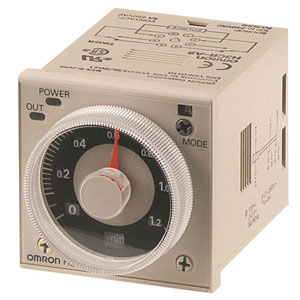
Omron H3CR-G8EL-31 AC100-120 Timer
The Omron H3CR-G8EL-31 AC100-120 Timer is built for dependable timing control with an allowable voltage variable range of 85 to 110% of the power supply voltage and an operation start voltage of 10% max. of rated supply voltage. It supporting 4 time ranges for dependable performance. Designed for Star-delta operation, and an 8-pin round socket (special terminal arrangement) connection. Manufactured by Omron, listed under Omron Timers, and part of the H3CR Series.

| Brand | Omron |
| Product | Timers |
| Model Number | H3CR-G8EL-31 AC100-120 |
Omron H3CR-G8EL-31 AC100-120 Timer - Technical Specifications
| Specification | Value |
|---|---|
| Rated power supply voltage | 100/110/120 VAC 50/60 Hz |
| Allowable voltage variable range | 85 to 110% of the power supply voltage |
| Power Consumption | Approx. 6 VA (at 120 VAC) Approx. 2.6 W (at 120 VAC) |
| Operation Start Voltage | 10% max. of rated supply voltage |
| Number of Times Ranges | 4 |
| Opeation Mode | Star-delta |
| Control Output Type | Time-limit: SPST-NO (Start operation circuit) SPST-NO (Delta operation circuit) ,Instantaneous: SPST-NO |
| Control output (Contact output) | Resistive load: 250 VAC 5 A (cosφ=1)/5 A at 30 VDC Minimum applicable load: 10 mA at 5 VDC (failure level: P Reference value) |
| Operating resetting | Time-limit operation/Self-reset |
| Ambient temperature range | Operating: -10 to 55 ℃ (with no icing) Storage: -25 to 65 ℃ (with no icing) |
| Ambient humidity range | Operating: 35 to 85% |
| Accuracy of operating time | ±0.2% FS max |
| Setting error | ±5% FS ±50 ms max. |
| Influence of voltage | ±0.2% FS max. |
| Influence of temperature | ±1% FS max |
| Insulation resistance | 100 MΩ min. (at 500 VDC) |
| Dielectric strength | Between current carrying metal parts and non-current carrying metal parts: 2,000 VAC 50/60 Hz 1 min Between control output terminals and operating circuit: 2,000 VAC 50/60 Hz 1 min Between contacts of different polarity: 2,000 VAC 50/60 Hz 1 min Between non-continuous contacts: 1,000 VAC 50/60 Hz 1 min |
| Impulse withstand voltage | Between power terminals: 5 kV Between current carrying terminals and exposed non-current carrying metal parts: 5 kV |
| Noise immunity | ±1.5 kV (between power terminals), square-wave noise by noise simulator (pulse width: 100 ns/1 µs, 1-ns rise) |
| Static immunity | Mulfunction: 8 kV, Destruction: 15 kV |
| Vibration resistance | Destruction: 10 to 55 Hz, 0.75 mm single amplitude each in 3 directions for 2 h Malfunction: 10 to 55 Hz, 0.5 mm single amplitude each in 3 directions for 10 min |
| Shock resistance | Destruction: 980 m/s2, 3 times each in 6 directions Malfunction: 294 m/s2, 3 times each in 6 directions |
| Life expectancy (relay output) | Electrical: 100,000 operations min. (5 A at 250 VAC, resistive load at 1800 operations/h) Mechanical: 20 million operations min. (under no load at 1,800 operations/h) |
| Degree of protection | IP40 (panel surface) |
| Connecting method | 8-pin round socket (special terminal arrangement) |
| Weight | Approx. 130 g |
Related Products