What Is The Working Principle Of A Multimeter?
Key Takeaway
The working principle of a multimeter depends on whether it is digital or analog.
A digital multimeter (DMM) uses a combination of analog and digital circuitry. It converts the input signal (voltage, current, or resistance) into a proportional voltage using analog circuits. This voltage is then converted into a digital value, which is displayed on the screen. For resistance measurements, it uses the constant current method, where a known current is passed through the device under test, and the voltage is measured. Resistance is then calculated using Ohm’s Law (R = V/I).
An analog multimeter operates on the D’Arsonval galvanometer principle. A moving coil in a magnetic field produces a deflection proportional to the measured current. The needle, attached to the coil, points to the corresponding value on a calibrated scale. Both types measure electrical properties but differ in precision and ease of use.
Overview of a Multimeter: Types and Functions
A multimeter is essentially a device that consolidates several electrical measurement tools into one compact unit. It measures three primary parameters: voltage, current, and resistance. More advanced models may also test continuity, diodes, capacitance, and frequency.
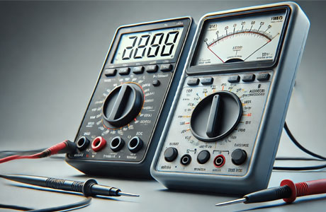
There are two main types of multimeters: analog and digital. Analog multimeters use a needle that deflects over a scale to show readings, offering real-time changes in measurements. Digital multimeters (DMMs), on the other hand, display readings on an LCD, providing higher precision and ease of use.
For electricians, technicians, and engineers, the type of multimeter chosen often depends on the specific application. Analog models are excellent for monitoring fluctuating signals, while digital models excel in precision and additional features. Both types share the same core principle: they measure electrical quantities by leveraging the interaction between voltage, current, and resistance.
Types and Functions H2: Understanding Analog vs. Digital Multimeter Principles
The working principle of a multimeter depends largely on whether it’s analog or digital.
Analog multimeters operate using a moving-coil galvanometer. This device generates a magnetic field when current passes through a coil. The interaction between this magnetic field and a fixed magnet causes the needle to deflect, indicating the measurement on a calibrated scale. Resistance is added or subtracted through series or shunt resistors to enable the device to measure different ranges.
Digital multimeters (DMMs) rely on analog-to-digital conversion (ADC). When an electrical parameter is measured, the device first converts it into an analog voltage if it’s not already. This voltage is then processed by the ADC, which transforms it into a digital signal. The resulting value is displayed on the screen.
Digital models often include advanced features like auto-ranging, data logging, and connectivity options, enhancing their usability. While both types serve the same fundamental purpose, digital multimeters offer superior accuracy and versatility, making them the preferred choice in modern applications.
Understanding Analog vs. Digital Multimeter Principles H2: How Voltage, Current, and Resistance Are Measured
The measurement of voltage, current, and resistance forms the foundation of a multimeter’s functionality.
Voltage Measurement: To measure voltage, the multimeter is connected in parallel with the circuit. This allows it to determine the potential difference between two points without altering the circuit’s operation. For DC voltage, the device measures the steady flow of electrons, while for AC voltage, it calculates the root mean square (RMS) value of the oscillating signal.
Current Measurement: Current is measured by connecting the multimeter in series with the circuit. This setup ensures that the entire current flows through the device. For higher currents, a clamp meter attachment may be used, allowing indirect measurement without breaking the circuit.
Resistance Measurement: Resistance is calculated by applying a small known current to the circuit and measuring the resulting voltage drop. Using Ohm’s Law (R=V/I), the multimeter determines the resistance value. This function is invaluable for testing components like resistors, fuses, and wires.
Each measurement relies on precise internal circuitry and calibration, ensuring the multimeter provides accurate results across a wide range of applications.
How Voltage, Current, and Resistance Are Measured H2: Key Components Inside a Multimeter
To understand how a multimeter works, it’s helpful to look at its internal components:
Rotary Switch: This allows users to select the desired measurement mode, such as voltage, current, or resistance.
Input Jacks: These are where the probes are connected. Different jacks may be used for low and high current measurements.
Resistors and Shunts: These components regulate current and voltage flow, ensuring accurate readings. Shunt resistors are particularly important for current measurement, as they allow the multimeter to handle high currents without damaging sensitive parts.
Analog-to-Digital Converter (ADC): In digital multimeters, this component converts the analog input signal into a digital output for display.
Microcontroller: This processes data from the ADC and controls advanced features like auto-ranging and data storage.
Display: For digital models, the LCD screen shows the readings. In analog models, a needle indicates the value on a scale.
Each component plays a specific role in ensuring the multimeter operates reliably and accurately, highlighting the sophistication of this seemingly simple tool.
Key Components Inside a Multimeter H2: Factors That Influence Accuracy in Multimeter Measurements
While multimeters are designed to be precise, several factors can influence their accuracy:
Quality of Components: High-quality resistors, shunts, and ADCs improve measurement precision. Low-cost models may compromise on these, leading to errors.
Calibration: Regular calibration ensures the multimeter provides accurate readings over time. Without it, even the best multimeters can drift from their original accuracy.
Environmental Conditions: Extreme temperatures, humidity, or electromagnetic interference can affect the performance of a multimeter. Using the device in stable conditions is critical for reliable results.
User Error: Incorrect probe placement, improper mode selection, or failing to account for circuit conditions can lead to inaccurate readings. Proper training and practice minimize these errors.
By understanding these factors, users can maximize the accuracy and reliability of their multimeters, ensuring consistent performance in any application.
Conclusion
The working principle of a multimeter revolves around its ability to measure voltage, current, and resistance with precision. Whether analog or digital, each type operates based on well-established principles of electronics and physics, supported by key components like resistors, shunts, and ADCs.
By understanding how a multimeter works and the factors that influence its accuracy, users can harness its full potential. Whether troubleshooting household circuits, maintaining industrial machinery, or testing electronic components, mastering this tool empowers engineers and technicians to work safely and effectively across diverse electrical scenarios.