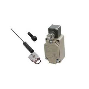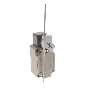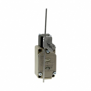
Omron WLCAL4-N Limit Switch
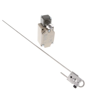
Omron WLCAL4-N is a WL Series limit switch with an adjustable rod lever measuring 350 to 380 mm, screw terminals, and a G½ conduit. This version is specified without an operation indicator. IP67 protection, 25 mΩ maximum initial contact resistance, and 100 MΩ minimum insulation resistance at 500 VDC are listed. The WLCAL4-N Long Adjustable Rod Lever belongs to the WL Series within the Omron Adjustable Lever Limit Switch Range from Omron Industrial Automation Components. Frequency is 50/60 Hz, with an operating temperature range from -10 to 80°C. Its rod lever, G½ screw terminals, and no-indicator configuration define the version.
| Brand | Omron |
| Product | Limit Switch |
| Model Number | WLCAL4-N |
Omron WLCAL4-N Limit Switch – Technical Specifications
| Specification | Value |
|---|---|
| Terminal Shape | Screw terminals (Conduit size: G½) |
| Pretravel Pt | 15±5° |
| Indicator | Without operation indicator |
| Ambient Temperature | -10 to +80°C (with no icing) |
| Ambient Humidity | 35 to 95%RH |
| Shock Resistance | Destruction: 1,000 m/s2 min. Malfunction: 300 m/s2 min. |
| Degree Of Protection | IP67 |
| Insulation Resistance | 100 MΩ min. (at 500 VDC) |
| Actuator | Adjustable rod lever: (350 to 380 mm) |
| Vibration Resistance | Malfunction: 10 to 55 Hz, 1.5-mm double amplitude |
| Contact Resistance | 25 mΩ max. (initial value for the built-in switch) |
| Rated Frequency | 50/60 Hz |
The Omron WLCAL4-N Limit Switch uses an adjustable rod lever specified from 350 to 380 mm, together with screw terminals and a G½ conduit. This version is listed without an operation indicator. Initial contact resistance is 25 mΩ maximum, while insulation resistance is 100 MΩ minimum at 500 VDC. Frequency is 50/60 Hz and IP67 protection is specified. Operating temperature ranges from -10 to 80°C with no icing, while relative humidity is 35 to 95%. These values provide the main electrical, connection, and environmental specifications behind the adjustable rod-lever configuration.
Malfunction vibration resistance covers 10 to 55 Hz at 1.5 mm double amplitude. Destructive shock resistance is 1,000 m/s² minimum and malfunction shock resistance is 300 m/s² minimum. A 15±5° value is present in the structured row, but the supplied extract does not show a clear field label for it, so no function is assigned to that value. The source also does not clearly provide a contact form, rated load, operating speed, operation mechanism, or durability figure. The most relevant exact-model terms therefore remain adjustable rod lever 350–380 mm, G½ screw terminals, no operation indicator, 25 mΩ initial contact resistance, 100 MΩ insulation resistance, and IP67 protection. For the related LED-indicator version with the same adjustable rod-lever range, see WLCAL4-LD-N.