| Number of channels | 4 analog outputs |
| Power supply connection | feed: 1 x M8 male socket, 4-pin, a-coded; downstream connection: 1 x M8 female socket, 4-pin, a-coded |
| Bit width in the process image | output: 4 x 16 bit data, optional: 4 x 8 bit control/status |
| Electrical isolation | channels/control voltage: yes, between the channels: no, control voltage/fieldbus: depends on the bus system |
| Digital peripheral signals | according to I/O type |
| Analog peripheral signals | according to I/O type |
| Configuration possibility | through KS2000 or the controller (explicit messaging) |
| Data transfer rates | automatic detection up to 500 kbaud |
| Bus interface | 1 x M12 plug, 5-pin |
| Data transfer medium | shielded copper cable, with power supply, typ. 2 x 2 x 0.25 mm² |
| Power supply | control voltage: 24 V DC (-15%/+20%); load voltage: according to I/O type |
| Box supply current | 45 mA + current consumption of sensors, max. 0.5 A |
| Auxiliary power current 1 | according to I/O type |
| Distance between stations | 500 m 250 m 100 m |
| Vibration/shock resistance | conforms to EN 60068-2-6/EN 60068-2-27 |
| EMC immunity/emission | conforms to EN 61000-6-2/EN 61000-6-4 |
| Protect. rating/installation pos. | IP65/66/67 (conforms to EN 60529)/variable |
| Approvals/markings | CE, UL |
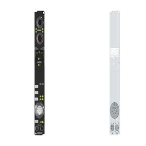
| Housing - Dimensions (W x H x D) | 30 mm x 175 mm x 26.5 mm |
| Housing - Material | PA6 (polyamide) |
| Housing - Installation | 2 fixing holes 3.5 mm diameter for M3 |
| Output connections | M12, screw type |
| Resolution | 16 bit |
| Measurement error/uncertainty | < ±0.1% (relative to full scale value) |
| Conversion time | < 4 ms |
| Nominal voltage | 24 V DC |
| Signal current | -10/0â¦10 V |
| Actuator supply | from the auxiliary voltage UP |